Basic Concepts
An electrical section break can be simply understood as a “zone manager” for the overhead contact line power supply system; its primary function is to divide a long stretch of overhead contact lines into multiple independent power supply sections by installing devices that provide both electrical and structural isolation. Consequently, the specific section where the overhead contact line is electrically separated is referred to as an electrical section break.
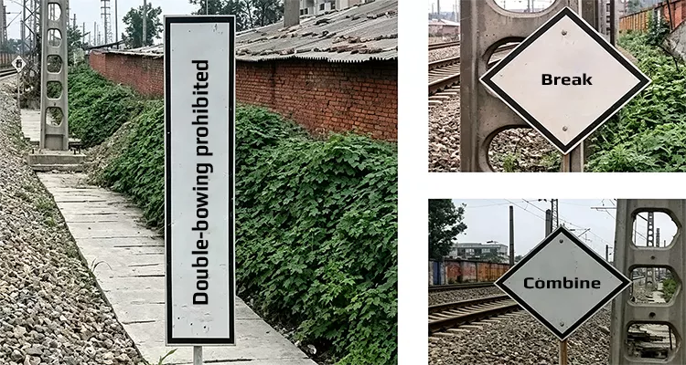
An electric traction no-stopping zone is not a standalone technical device; rather, it is a designated area—defined by the structure of electrical sectioning—where electric locomotives and electric multiple units (EMUs) are prohibited from stopping, serving to warn train drivers against halting within this zone.
To prevent severe three-phase unbalance in the power grid, electrified railways employ phase-separation and sectionalized power supply systems. A neutral section—a dead zone typically 200 to 900 meters in length—is installed between power supply arms fed by different phases; electric locomotives and electric multiple unit (EMU) trains must briefly cut off power and coast when passing through these sections.
Electrical Sectioning and No-Stopping Zones
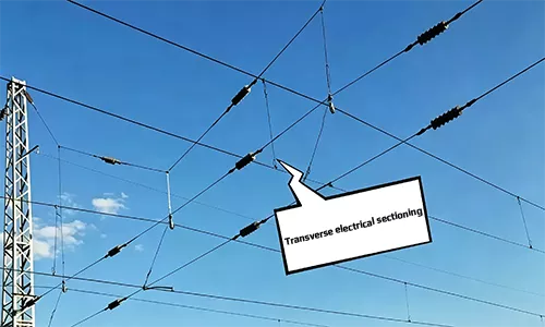
Based on their mode of operation, electrical sectioning can be classified into transverse and longitudinal types. Transverse electrical sectioning is applied between the various catenary lines within a station yard, while longitudinal electrical sectioning is applied to the catenary lines along the track.
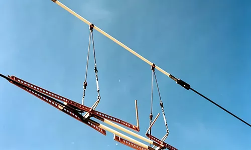
Lateral electrical sectioning refers to the electrical separation between different overhead contact line tracks; it is used to electrically sectionalize the contact lines serving the up and down tracks of double-track lines, as well as the various tracks within station yards. Common examples of lateral electrical sectioning include “no-stop zones” for electric locomotives and section insulators; both types constitute in-phase electrical sectioning.
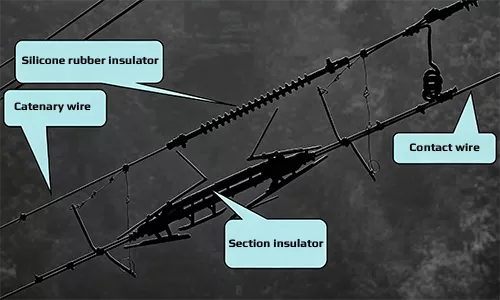
Section insulators and “no-stop” zones for electric locomotives divide the overhead contact line of a single-phase power supply unit into separate supply sections, facilitating operations such as electrical isolation between up- and down-bound tracks, yard power distribution, locomotive servicing, and cargo loading/unloading. These electrical sections help limit the scope of power outages during maintenance or malfunctions, thereby minimizing disruptions to transport operations. They also ensure continuous power supply as electric locomotives (or EMUs) traverse the section boundaries, while reducing the frequency of manual adjustments required by drivers during the crossing.
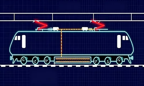
A drawback of the configuration used for lateral electrical sectioning is that both the “no-stop zones” for electric locomotives and the section insulators facilitate only in-phase electrical separation. When an electric locomotive or electric multiple unit (EMU) passes through these zones or insulators, the pantograph bridges the two power supply units; since the voltages at either end of the electrical section are not identical, a potential difference exists, resulting in the flow of current. If the train remains stationary within the electrical section for an extended period, the pantograph contact strip is subjected to continuous electro-thermal stress. Under these conditions, the resistance of the contact strip approaches zero; according to Ohm’s law, the short-circuit current becomes extremely high (approaching infinity), causing heat generation to rise exponentially. This can instantly burn out the overhead contact line or trigger a trip at the substation—which is precisely why EMUs are strictly prohibited from stopping in these no-stop zones or at section insulators.
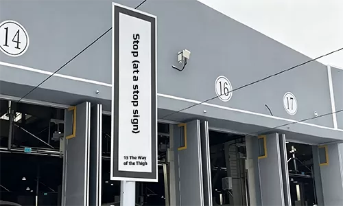
Railway operational regulations stipulate that when an EMU train stops outside the depot entrance to await a signal, it must not pass the “EMU Mandatory Stop” marker. This is because a section insulator is located outside the entrance; stopping incorrectly could result in the pantograph bridging the two power supply units across the insulator for an extended period. Section insulators are also installed on tracks within stations and depots; arcing (sparks) is clearly visible when an EMU passes through them, and on certain depot tracks, the main circuit breaker (VCB) may even trip automatically.
Longitudinal electrical sectioning refers to the division of the overhead contact line along the direction of the track—for instance, the separation between adjacent power supply arms. Common examples include phase-break sections created by insulators or overlap spans; the following discussion examines longitudinal sectioning in the context of phase-break sections.
Electric phase separation
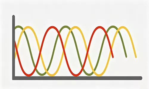
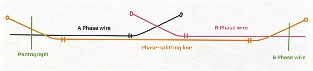
In AC traction power supply systems, to balance the loads across phases A, B, and C of the power grid, power is generally supplied to the phases in rotation; consequently, the phases must be electrically isolated from one another—a practice known as phase separation.
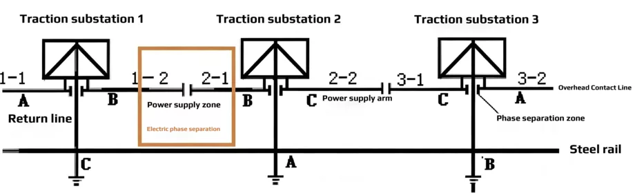
High-speed railway electric phase separation typically employs an insulated overlap arrangement featuring two breaks and an air-insulated neutral section. This configuration enables the separation of different electrical phases; an isolating switch is installed between the neutral section and the adjacent anchor section (on the side from which the train approaches). If an electric multiple unit (EMU) comes to a halt within the dead section—and provided insulation requirements relative to the approaching anchor section are met—closing the isolating switch (GK) restores power to the train, allowing it to exit the dead section. The neutral anchor section is neither energized nor grounded, serving instead as a transition zone for passing trains.
The primary drawback of neutral sections is the requirement for trains to cut off power while passing through; this not only increases the operational workload for the driver but may also cause certain electric multiple units (EMUs) to lose their constant-speed control functionality. During cross-section power supply operations, all trains on adjacent power supply arms must come to a halt and lower their pantographs. This is because the GK isolating switch is closed and the neutral section is energized; consequently, if a following train were to pass through the neutral section, its pantograph would directly short-circuit power supply units of different phases, potentially triggering an accident involving damage to the overhead contact system. Furthermore, if a train maintains an excessively low speed or stops unexpectedly while traversing a long, steep uphill grade, it risks becoming stranded within the unpowered neutral section.
Taking a six-span anchored articulated phase-break section as an example, the neutral zone is approximately 190 meters long, while the actual dead zone (de-energized section) is only 22 meters. If a coupled multiple-unit trainset operates with the leading unit raising its rear pantograph and the trailing unit raising its front pantograph—or if the trainset raises both pantographs simultaneously—the pantograph contact strips will directly short-circuit Phase A and Phase B via the neutral wire. This poses a high risk of burning out the overhead contact line, which is why the use of dual pantographs is prohibited for trains passing through electric phase-break sections. To alert the train to close its main circuit breaker and restore the electrical connection between the traction circuit and the overhead contact line after exiting the dead zone, a “power-on” marker is installed at the exit end of the phase-break section.
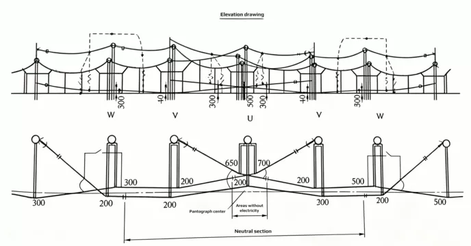
Railway operational regulations require the installation of a “power-off” marker ahead of the catenary neutral section; this marker is placed on the second support structure preceding the start of the neutral section (with a distance of at least 80 meters between that structure and the start of the section). Additionally, a “power-on” marker is installed beyond the neutral section on a catenary support structure located approximately 400 meters past the end of the section (with a distance of at least 400 meters between that structure and the end of the section).